3D Graphics Programming with QuickDraw 3D 1.5.4
Previous | QD3D Book | Overview | Chapter Contents | Next |
Using Polyhedrons
The polyhedron is the primitive of choice for most programming situations, as well as for the creation and distribution of editable model files. Thus if your application requires the creation, conversion, or distribution of polyhedral models, you should produce them in polyhedron format instead of mesh or trimesh. User applications such as modelers and animation tools should also generally manipulate polyhedrons. Plug-in renderers are required to support certain basic primitives (triangles, points, lines, and markers) and are strongly urged to support the polyhedron as well.
The polyhedron format gives you these features:
- It can easily represent many different polyhedral models in a space-efficient fashion.
- It's capable of fast rendering.
- It's highly consistent with the rest of the QuickDraw 3D API.
- Attributes can be attached in whatever combination is appropriate for the model.
Polyhedrons make geometric editing operations, which change the positions of existing vertices, easy and convenient. In immediate mode, you can simply alter a point's position in the array in the polyhedron data structure and render the shape again. In retained mode, several function calls let you change vertex locations, as well as providing the usual assortment of Get and Set calls for attributes, faces, face attributes, and so on.
You can use topological editing operations to change the relationships between vertices, faces, edges, and the whole polyhedron. However, the addition or deletion of vertices, faces, or edges may require reallocation of one or more of the polyhedron's arrays. Because the polyhedron has a public data structure, these operations are possible in both immediate mode and retained mode. If adding and deleting vertices, faces, or edges aren't the primary operations required for using the polyhedron, array reallocation will not be a problem; if they are, you should use the mesh primitive instead.
The polyhedron uses memory and disk space efficiently because shared locations and attributes are stored only once and only those parts that logically require attributes get them. This produces good I/O speed, although, as with all geometric primitives, the addition of textures can increase I/O time significantly. The polyhedron also features superior rendering speed because its vertices are shared.
Creating a Polyhedron
The normal way to make a polyhedron is to create an array of points and a list of triangular faces that organize the points. Each face consists of a list of indices into the list of vertices, forming a polygon with one level of array-based indirection. If there is more than one face, the vertices can be shared by reusing the same array indices in each face. This allows the graphics system to run faster because the same point doesn't have to be transformed or shaded more than once, and it saves storage space. In addition, because two or more faces share only one real vertex, this format makes it easier to do interactive editing programming.
Polyhedrons--objects of type kQ3GeometryTypePolyhedron --implement this process in a way that is consistent with the other QuickDraw 3D primitives. Its basic component is the vertex of type TQ3Vertex3D , an {x, y, z} location with an attribute set. The vertices of adjacent triangular faces are shared simply by using the same vertex indices. Also, sets of attributes may be shared like other objects in QuickDraw 3D:
vertex->attributeSet = Q3Shared_GetReference(otherVertex->attributeSet);
Vertices can contain the same locations, but need not share attributes. This can be useful, for example, when creating a polyhedron that is generally smooth but has some edges or corners where you want a discontinuity. For example, consider the cross section of a polyhedron shown in Figure 12 , which has vertices sharing locations but not attributes.
In Figure 12 , each location is shared, and vertices at positions A, B, D, and E share normals, while the vertices at position C share the location but not the normal. So when smooth-shaded, the object has an edge or corner at position C but appears smooth elsewhere.
Figure 12 Cross-section of a polyhedron

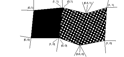
Because values in an attribute set apply to all vertices or faces sharing that attribute set, operations on it will affect all these elements. For example, you can associate a single texture with a group of faces by simply giving each face a shared reference to the texture-containing attribute set. For a single texture to span a number of faces, you need to make sure their shared vertices share texture coordinates. You can do this by making shared vertices of faces that are spanned by a single texture use the same attribute set, as shown in Figure 13 .
Figure 13 Applying textures that span several faces

Besides an attribute set for the face, the three vertices defining a face of a polyhedron are in an array of size 3. The polyhedron also uses an enumerated type that defines which edges are drawn and which not:
typedef enum TQ3PolyhedronEdgeMasks {

    kQ3PolyhedronEdgeNone   = 0,

    kQ3PolyhedronEdge01     = 1 << 0,

    kQ3PolyhedronEdge12     = 1 << 1,

    kQ3PolyhedronEdge20     = 1 << 2,

    kQ3PolyhedronEdgeAll    = kQ3PolyhedronEdge01 |

                              kQ3PolyhedronEdge12 |

                              kQ3PolyhedronEdge20

} TQ3PolyhedronEdgeMasks;
typedef unsigned long TQ3PolyhedronEdge;
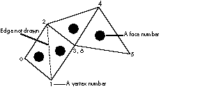
By OR-combining these flags you can select which edges of a particular triangle you want drawn. For example, if you're using a wireframe renderer to draw an object like the one shown in Figure 14 , you wouldn't have to show the "internal" edges, just the edges that represent the true border of the face. For face 0 in Figure 14 , you could specify that you want to display only the edges between vertices 0 and 1 and vertices 2 and 0, leaving undrawn the edge between vertices 1 and 2. You'd do this by specifying (kQ3PolyhedronEdge01 | kQ3PolyhedronEdge20) as the edge mask.
Figure 14 Wireframe polyhedron

All the information discussed so far is collected in this data structure:
typedef struct TQ3PolyhedronTriangleData {

    unsigned long       vertexIndices[3];

    TQ3PolyhedronEdge   edgeFlag;

    TQ3AttributeSet     triangleAttributeSet;

} TQ3PolyhedronTriangleData;
An alternative to using a mask to specify the edges is to create a list of edges for the entire polyhedron. If the renderer draws the edges (or lines, in the case of a wireframe renderer) from an edge list, the renderer can transform the points just once each and draw each edge just once, resulting in much faster rendering. The renderer ignores the edge flags in the face data structure if an array of these edges is present:
typedef struct TQ3PolyhedronEdgeData {

    unsigned long       vertexIndices[2];

    unsigned long       triangleIndices[2];

    TQ3AttributeSet     edgeAttributeSet;

} TQ3PolyhedronEdgeData;
As shown in Figure 15 , the vertexIndices field specifies indices into the vertex array, one for the vertex at each end of each edge.
Figure 15 Filling out a polyhedron's edge data structure

The triangleIndices field shown in Figure 15 specifies indices into the array of faces. You need to provide the indices to the faces that share an edge because performing correct backface removal requires that the edge be drawn only if at least one of the faces that it's part of is facing forward.
The edgeAttributeSet field allows the application to specify the color and other attributes of edges independently. If no attribute is set for an edge, the attributes are inherited from the geometric object, or from the view's state if that's not present. Every edge must have two points, but edges may have one or two faces adjacent to them; those with just one are on a boundary of the object. To represent a boundary in an array-based representation, you use the identifier kQ3ArrayIndexNULL as a face index for the side of an edge that has no face attached to it.
When going from the vertex at index 0 to the vertex at index 1 in Figure 15 , the 0th face is to the left. If possible, fill out your data structures to conform to this practice. Other code may want to traverse the edge list and be assured of knowing exactly which face is on which side of each edge.
The following is the entire polyhedron data structure:
typedef struct TQ3PolyhedronData {

    unsigned long               numVertices;

    TQ3Vertex3D                 *vertices;

    unsigned long               numEdges;

    TQ3PolyhedronEdgeData       *edges;

    unsigned long               numTriangles;

    TQ3PolyhedronTriangleData   *triangles;

    TQ3AttributeSet             polyhedronAttributeSet;

} TQ3PolyhedronData;
Listing 7 shows the code that creates the four-faced polyhedron shown in Figure 14 .
Listing 7 Creating a four-faced polyhedron
TQ3ColorRGB         color;

TQ3PolyhedronData   polyhedronData;

TQ3GeometryObject   polyhedron;

TQ3Vector3D         normal;
static TQ3Vertex3Dvertices[7] = {

    { { -1.0,  1.0,  0.0 }, NULL },

    { { -1.0, -1.0,  0.0 }, NULL },

    { {  0.0,  1.0,  1.0 }, NULL },

    { {  0.0, -1.0,  1.0 }, NULL },

    { {  2.0,  1.0,  1.0 }, NULL },

    { {  2.0, -1.0,  0.0 }, NULL },

    { {  0.0, -1.0,  1.0 }, NULL }

};
TQ3PolyhedronTriangleData   triangles[4] = {

    {  /* Face 0 */

        { 0, 1, 2 },                                /* vertexIndices */

        kQ3PolyhedronEdge01 | kQ3PolyhedronEdge20,  /* edgeFlag */

        NULL                                 /* triangleAttributeSet */

    },

    {  /* Face 1 */

        { 1, 3, 2 },

        kQ3PolyhedronEdge01 | kQ3PolyhedronEdge12,

        NULL

    },

    {  /* Face 2 */

        { 2, 3, 4 },

        kQ3PolyhedronEdgeAll,

        NULL

    },

    {../* Face 3 */

        { 6, 5, 4 },

        kQ3PolyhedronEdgeAll,

        NULL

    }

};
/* Set up vertices, edges, and triangular faces. */

polyhedronData.numVertices      = 7;

polyhedronData.vertices         = vertices;

polyhedronData.numEdges         = 0;

polyhedronData.edges            = NULL;

polyhedronData.numTriangles     = 4;

polyhedronData.triangles        = triangles;
/* Inherit the attribute set from the current state. */

polyhedronData.polyhedronAttributeSet = NULL;
/* Put a normal on the first vertex. */

Q3Vector3D_Set(&normal, -1, 0, 1);

Q3Vector3D_Normalize(&normal, &normal);

vertices[0].attributeSet = Q3AttributeSet_New();

Q3AttributeSet_Add(vertices[0].attributeSet, kQ3AttributeTypeNormal,

    &normal);
/* Same normal on the second. */

vertices[1].attributeSet =

    Q3Shared_GetReference(vertices[0].attributeSet);
/* Different normal on the third. */

Q3Vector3D_Set(&normal, -0.5, 0.0, 1.0);

Q3Vector3D_Normalize(&normal, &normal);

vertices[2].attributeSet = Q3AttributeSet_New();

Q3AttributeSet_Add(vertices[2].attributeSet, kQ3AttributeTypeNormal,

    &normal);
/* Same normal on the fourth. */

vertices[3].attributeSet =

    Q3Shared_GetReference(vertices[2].attributeSet);
/* Put a color on the third triangle. */

triangles[3].triangleAttributeSet = Q3AttributeSet_New();

Q3ColorRGB_Set(&polyhedronColor, 0, 0, 1);

Q3AttributeSet_Add(triangles[3].triangleAttributeSet,

    kQ3AttributeTypeDiffuseColor, &polyhedronColor);
/* Create the polyhedron object. */

polyhedron = Q3Polyhedron_New(&polyhedronData);
... /* Dispose of attributes created and referenced. */
Listing 8 shows code that specifies the edges of the polyhedron shown in Figure 14 , but using the optional edge list. It is added to the code in Listing 7 . When using an edge list, you would set the edge flags in the triangle data of Listing 7 to a legitimate value, such as kQ3EdgeFlagAll , that will be ignored.
Listing 8 Using an edge list to specify the edges of a polyhedron
polyhedronData.numEdges     = 8;

polyhedronData.edges        = malloc(8 * sizeof(TQ3PolyhedronEdgeData));
polyhedronData.edges[0].vertexIndices[0]    = 0;

polyhedronData.edges[0].vertexIndices[1]    = 1;

polyhedronData.edges[0].triangleIndices[0]  = 0;

polyhedronData.edges[0].triangleIndices[1]  = kQ3ArrayIndexNULL;

polyhedronData.edges[0].edgeAttributeSet    = NULL;
polyhedronData.edges[1].vertexIndices[0]    = 2;

polyhedronData.edges[1].vertexIndices[1]    = 0;

polyhedronData.edges[1].triangleIndices[0]  = 0;

polyhedronData.edges[1].triangleIndices[1]  = kQ3ArrayIndexNULL;

polyhedronData.edges[1].edgeAttributeSet    = NULL;
polyhedronData.edges[2].vertexIndices[0]    = 1;

polyhedronData.edges[2].vertexIndices[1]    = 3;

polyhedronData.edges[2].triangleIndices[0]  = 1;

polyhedronData.edges[2].triangleIndices[1]  = kQ3ArrayIndexNULL;

polyhedronData.edges[2].edgeAttributeSet    = NULL;
polyhedronData.edges[3].vertexIndices[0]    = 3;

polyhedronData.edges[3].vertexIndices[1]    = 2;

polyhedronData.edges[3].triangleIndices[0]  = 1;

polyhedronData.edges[3].triangleIndices[1]  = 2;

polyhedronData.edges[3].edgeAttributeSet    = NULL;
... /* Specify the rest of the edges. */
© 1997 Apple Computer, Inc.
Previous | QD3D Book | Overview | Chapter Contents | Next |